|
|||||||||||||||||
 |
 |
 |
|||||||||||||||
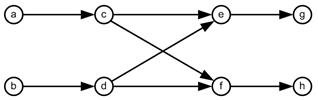
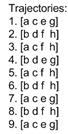
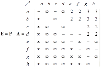
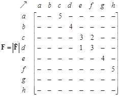
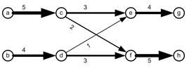
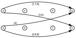
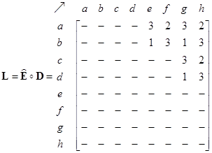
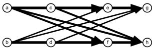
| Weaving Section Numerical Example Suppose we have a simple weaving section consisting of 8 nodes and 8 links. For simplicity, without losing generality, we consider only 9 agents and generate 9 ordinal trajectories to be put into the network. The trajectories consist of 4 types in this simple network, but we repeat some of the trajectories. The adjacency matrix, the network and trajectories are given in the following figure. Zeroes in the matrix are deleted to enhance the pattern of non-zero entries. The non-zero entries are located on the upper diagonal to indicate that it is acyclic directed graph. The upper triangular property, however, is very much dependent on the labeling of the nodes. For example, if we swapped the labeling of the nodes ‘a’ and ‘h’, then the non-zero entries will not be restricted to the upper triangular, even though the graph is still a directed acyclic graph. See Buckley &Harary (1990) for proof that acyclic directed graph can be labeled as upper triangular of the adjacency matrix.
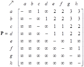
From the network structure, the path matrix isgiven below as computed using a simple breadth-first search approach using the adjacency matrix as input. Again, the zeroes are deleted from the matrices to enhance the view. Infinite elements indicate there exists no path between the two nodes. The maximum non-infinity entries represent the diameter of the network (which is 3 in this case). Binarized path matrix is the matrix that results from transforming all non-zero and non-infinity elements into one.
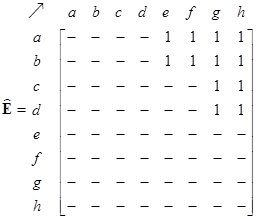
On the network structure, we can also define external matrix as the difference between path matrix and adjacency matrix. In the binarized external matrix, all non-zero and non-infinity elements of external matrix are also transformed to one
Now we discuss how the network is
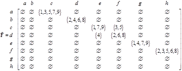
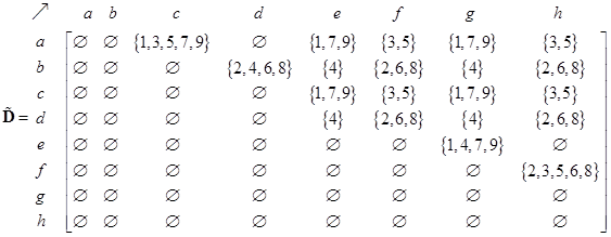
utilized by putting ordinal graph trajectories into the network. Matrix-set
(with tilde) is a matrix in which entries are sets of trajectories. The matrix
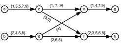
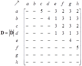
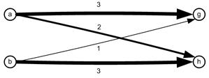
When we count the number of elements of sets of trajectory ids on each link, we get the flow matrix. Associated with the flow matrix is the flow pattern on each link as shown in the figure below. The number on each link is the explicit number of trajectories passing through that particular link. We also put the number visually as the weight of the arrow as flow pattern.
A trajectory passes through a
sequence of nodes from a source to a sink. Any ordered two nodes of the node
sequence of a trajectory can be seen as origin and destination nodes. For
instance, trajectory #1 of a->c->e->g will produce origin destination
pair nodes of {a->c, a->e, a->g, c->e, c->g, e->g}. Putting
these OD pair nodes into matrix produces origin-destination-set matrix
The tilde notation represents a matrix whose elements are sets instead of scalar values. If we count the number of elements in each set in the matrix, we get the OD matrix
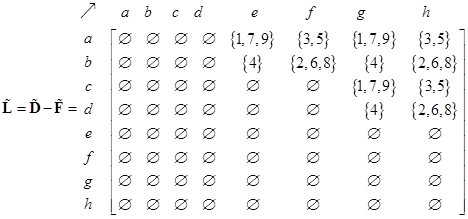
Since
Now we exclude matrix set
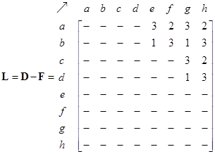
Then we get the count of the elements in each set in the matrix to obtain
The Hadamard product of the binarized eternal matrix with the OD matrix will also produce the desire line matrix because there is no alternative route flow. The desire line pattern visualization is also shown below.
These tutorial is copyrighted. Preferable reference for this tutorial is Teknomo, Kardi. (2013) Relationship between Generalized Origin Destination and Flow Matrix – A Tutorial |
|||||||||||||||
|
||||||||||||||||
|
||||||||||||||||